My plan with the second paralleled pack is to do something similar to Dani on myimiev fourms (http://myimiev.com/forum/viewtopic.php?f=23&t=3074&start=20) who put a parallel pack in the rear seats of an imiev. I will be putting the second pack in the boot of the BMW.
1. Mount the battery frame I made in the boot securely.
There are 6 bolts holding the battery frame to the chassis, 4 through the floor of the boot and 2 through the bulkhead behind the rear seats.
2. Sorting out the BMS wiring.
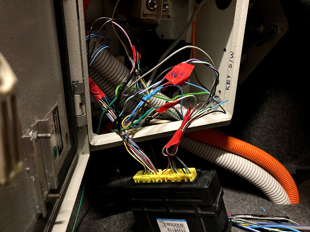
To get the BMS wiring that goes from the pack to the right side plug on the BMS master unit pull the wiring loom under the car from the second donor i-MIEV and then isolate the BMS wiring from the loom. One of the connectors from the pack will lead to the ECU, this is the plug for quick charging and we wont be needing this for the rear pack.
On the circular plug to the pack there is 12v ignition to the center wire and ground on the black wire the other wires that lead to the ECU are for the contactors and mid-pack disconnect jumper.
To get the BMS wiring that goes from the pack to the left side plug on the BMS master unit it all needs to be cut out as the wires will be re-soldered once in the boot. Here is the pin-out of the BMS master for the 10.5Kwh i-MIEV.you can get this info from the workshop manual but I find it makes it easier to wrap my head arround it if I write it down.
The conduit section is for the wires going to the front of the car, those being 12v Battery, 12v Ignition, CAN H, CAN L, and K-line to the ECU. These are the only external connections needed for the BMS master unit.
The rear contactors are activated with the same 12v signal as the ignition signal for the ECU in the rear, which is provided through a relay in the front of the car activated by the 12v for the main negative contactor.
All tidied up!
3. Now to bolt and wire in the batteries!
First the rear mid pack fuse.
Then all the modules and their BMS and HV wiring. The Anderson connector is being used as an emergency/maintenance mid pack disconnect.
4. Now to test!
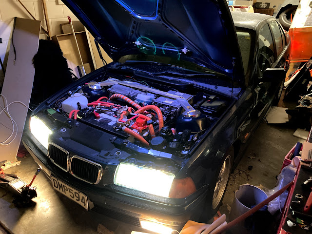
After getting the two packs to within 0.1V of each other i plugged in the rear contactor... and it works! plus the addition of a strut bar and LEDs hooked up to a bonnet switch to light it all up.
I will eventually hook the CAN and K-line from both the BMUs into a 2 position 9 pin switch with the CAN and K-line to the ECU being on the common pins. which should enable me to flick between the two BMUs while monitoring them through the OBD2 port.


