Tuesday, 1 June 2021

CHAdeMO with two packs in parallel

To get quick charging going I should be able to just wire up the QC contactor to the paralleled packs and plug in the communication wires.

The QC cables come up on the bottom left of the image and bolt into the QC contactor.


Initially the quick charging port didn't initialise and after a lot of digging through the service manuals and trouble shooting I found the QC contactor relay to be faulty. After replacing it with a spare relay from the parts car CHAdeMO was working with the MiEV power box I was using to test the port.

Now that I knew the port was working I went for a drive to first drain the battery and test the quick charging.

Here you can see the Chademo is taking power in at 99A just below the 100A limit of the contactor, and the front pack is charging at about 49A.

All the systems seem to be ok with arround half of the energy coming in just disappearing! (into the rear battery pack) 


Sunday, 30 May 2021

i-MIEV battery packs in parallel

 My plan with the second paralleled pack is to do something similar to Dani on myimiev fourms (http://myimiev.com/forum/viewtopic.php?f=23&t=3074&start=20) who put a parallel pack in the rear seats of an imiev. I will be putting the second pack in the boot of the BMW.

1. Mount the battery frame I made in the boot securely.

There are 6 bolts holding the battery frame to the chassis, 4 through the floor of the boot and 2 through the bulkhead behind the rear seats.


 2. Sorting out the BMS wiring.

To get the BMS wiring that goes from the pack to the right side plug on the BMS master unit pull the wiring loom under the car from the second donor i-MIEV and then isolate the BMS wiring from the loom. One of the connectors from the pack will lead to the ECU, this is the plug for quick charging and we wont be needing this for the rear pack.

On the circular plug to the pack there is 12v ignition to the center wire and ground on the black wire the other wires that lead to the ECU are for the contactors and mid-pack disconnect jumper.

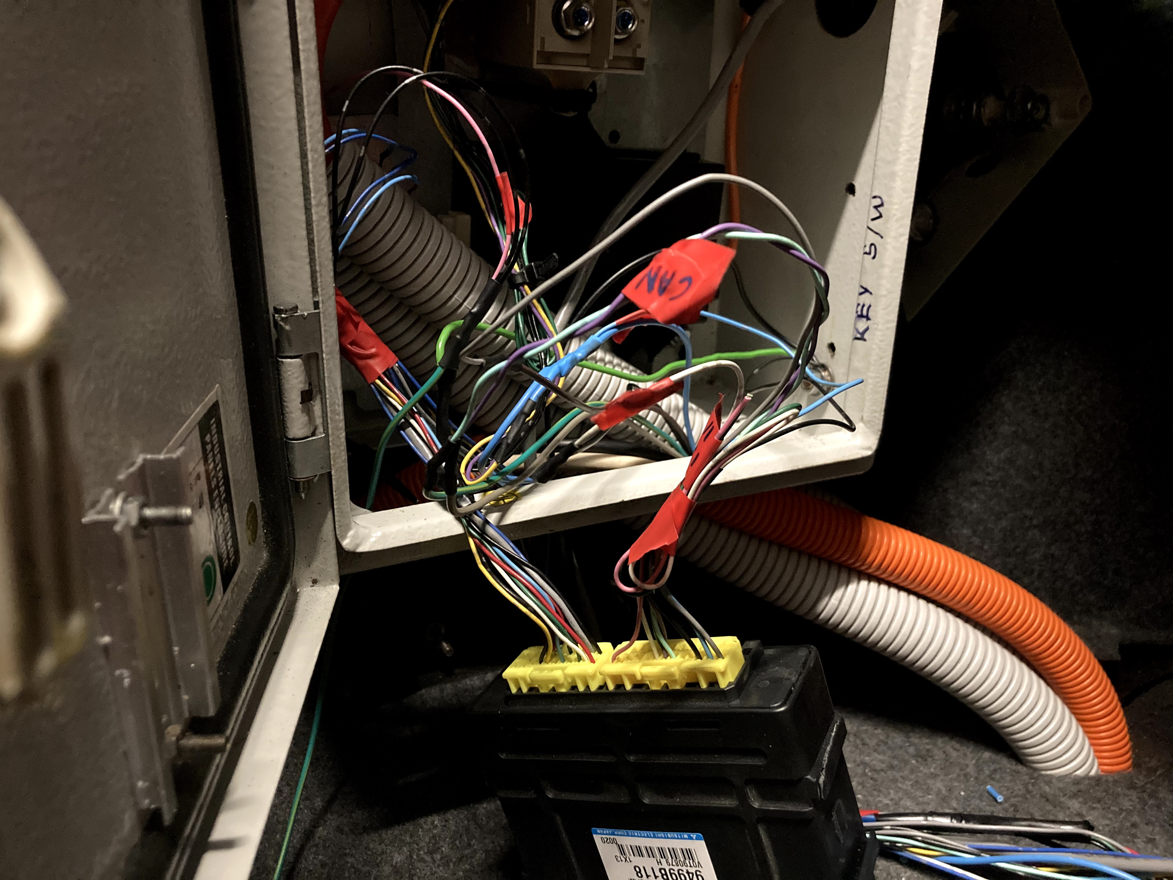
To get the BMS wiring that goes from the pack to the left side plug on the BMS master unit it all needs to be cut out as the wires will be re-soldered once in the boot. Here is the pin-out of the BMS master for the 10.5Kwh i-MIEV.you can get this info from the workshop manual but I find it makes it easier to wrap my head arround it if I write it down.

The conduit section is for the wires going to the front of the car, those being 12v Battery, 12v Ignition, CAN H, CAN L, and K-line to the ECU. These are the only external connections needed for the BMS master unit.

 The rear contactors are activated with the same 12v signal as the ignition signal for the ECU in the rear, which is provided through a relay in the front of the car activated by the 12v for the main negative contactor.
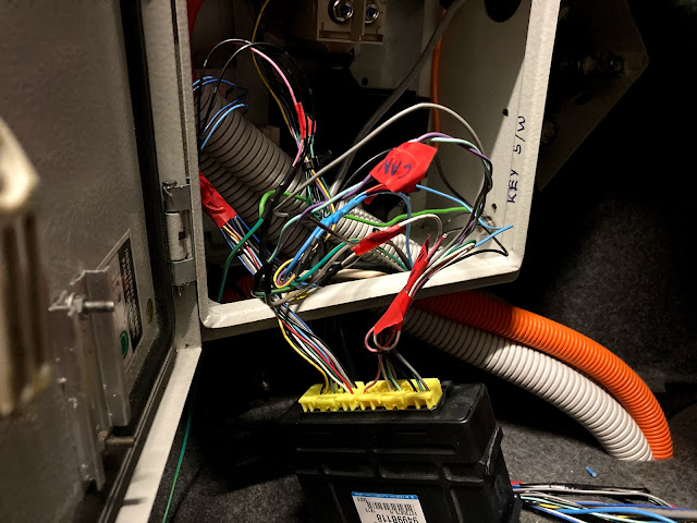
 All tidied up!


3. Now to bolt and wire in the batteries!

  First the rear mid pack fuse.


Then all the modules and their BMS and HV wiring. The Anderson connector is being used as an emergency/maintenance mid pack disconnect.


4. Now to test!

After getting the two packs to within 0.1V of each other i plugged in the rear contactor... and it works! plus the addition of a strut bar and LEDs hooked up to a bonnet switch to light it all up.

 I will eventually hook the CAN and K-line from both the BMUs into a 2 position 9 pin switch with the CAN and K-line to the ECU being on the common pins. which should enable me to flick between the two BMUs while monitoring them through the OBD2 port.


Thursday, 26 November 2020

Finally Driving and a CAN reading Arduino

 Here is a short and sweet video of the BMW taking off in first gear. I may have held the brake down a bit too long...


Now that i have got the car running and driving we can begin to build up the code and test the Arduino reading from the CAN and driving the dash. While I wrote the code to run the dash initially, integrating the CAN reading function was just way above my programming level, so I got the help of a friend  to help me finish it off. 

He has been working on prototypes for a while and has uploaded the final code to GitHub here: https://github.com/Damo-Chasey/16x2-LCD-fuel-gauge-and-BMW-Dash_controller


Tuesday, 24 November 2020

Arduino dash control

To get started with the arduino dash control I first controlled the dash using the Arduino with set values rather than values read from the CAN bus of the imiev.
This video here shows the startup sweep I made the tacho do, unfortunately there isnt a quick enough response from the temp and fuel gauges to do this to them too.

 
Here is the code I made to run the Tacho gauge, unfortunately I wasn't able the get the MPG gauge working at all and struggled to get the fuel gauge to be consistent so i wont be using them and instead will be using an LCD screen later on to display the data. The code to run the Temp gauge is in there its just not currently being used.
 
#include <Tone.h>  // "Tone by Brett Hagman" in Library Manager


//const byte E36TachPin =      2;  // Tone
//const byte E36MPGPin =       9;  // PWM  (Not valid PWM pin for Arduino UNO!)
//const byte E36FuelGagePin =  5;  // PWM
//const byte E36TempGagePin =  6;  // PWM


void setup()
{

  pinMode(5, OUTPUT); //Fuel
  pinMode(6, OUTPUT); //Temp
  pinMode(9, OUTPUT); //MPG
 
  //#####FUEL#####
   analogWrite(5, 165); //sets fuel to Full
    // 0=EMPTY, 10=E, 55=15L, 95=30L, 125=45L, 165=FULL
 
  //#####TEMP##### 
  analogWrite(6, 50); //sets temp to middle pos
   // 6=HOTFlashing 10=HighesTemp 15=HOTLightOn, 50=MID, 100=COLD
    // Use 10 - 100 for temp range, set 6 as a value for flashing HOT
 
  //#####TACH#####
    Tone E36TachTone;
    E36TachTone.begin(2);
    E36TachTone.play(31);
  //35=1k, 129=4k, 222=7k
  //28.5 31 31.53
  
  
  //RPM sweep
    for(int t=31; t<222; t++){
      E36TachTone.play(t);
      delay(2);
    }
    delay(500);
    for(int t=222; t>31; t--){
      E36TachTone.play(t);
      delay(2);
    }
    E36TachTone.play(31);


  //#####MPG#####
   // Tone E36MPGTone;
   // E36MPGTone.begin(9);
    //E36MPGTone.play(0);

}

void loop() {
  //#####TACH LOOP#####
    Tone E36TachTone;
 
  int RPM = 500;  //input RPM read from CAN here IF car is in ready state else stop RPM gauge
  int RPMt;
 
  RPMt = RPM/30.5;
 
  if (RPMt < 31){ //stops rpm gauge signal going below 31 Hz for idle(causes issues)
    RPMt = 31;
    }
 
  E36TachTone.play(RPMt);


  //#####MPG, TEMP, FUEL LOOP##### 
  //Tone E36MPGTone;
 
  //E36MPGTone.play(00);
      // analogWrite(5, 165); //Fuel
 
    //analogWrite(6, 50); //Temp
   
    //analogWrite(9, 0); //MPG

}


Monday, 2 November 2020

Installing the drivetrain and getting ready for a test drive

After getting the motor coupler machined and installed its now time to put everything together to test if it will drive!


Here's the motor coupler before it was machined and after. Now it has the I-MiEV spline pressed into it and has two grub screws stopping it from spinning in the coupler.


Connecting up the AC slow charging with cables more than capable of handling the maximum 32A current allowed by the on-board charger.


Prepping and Painting the fabricated brackets.

I filed down all rough/sharp edges on the brackets and wiped them down with acetone to prep for painting. I painted the brackets with a matte black rust preventing paint.

Before installing all the brackets and drive-train you can get a really good look at the conduits running to the rear of the car. They're nothing special, just a mix of solid and flexible conduit held on with a mix of pvc and metal brackets


Installing the drive-train, brackets , and components.

First off the transmission, motor, and coupler are bolted in.

Then the battery and motor supports are installed.

After that the 12v vacuum and power steering pump are installed above the motor, although they arent that visible due to all the cables and my great camera work.


The Motor Controller and On-board Charger/DC-DC with the coolant tank bolted to it are next to go in.

Then the bottom level of batteries are bolted to the bracket and connected together. The AC charging cables have also been connected to the OBC.

Finally the top layer of batteries, the HV cables, contactors, then some coolant and we are ready for a test charge and drive!


Saturday, 29 August 2020

Slowly making progress: August update

Things have been moving slowly on this project recently with Uni and two part-time jobs getting in the way, but I have managed to get some things tidied up and finished off.

I have re-installed the previous owners conduits under the car as they do not conform with current New Zealands LVVTA EV certification guidelines anymore as the old conduit was plain white and had both the positive and negative HV wires running through a single conduit which is a big no no. The new certification guidelines state positive and negative HV cables must be run through separate conduits and must be orange in colour, or obviously indicate there are HV cables inside with warning labels for example.

Old:

This is the old single conduit (folded in half), you could not see the orange cables at all when it was installed and nothing on the conduit indicated HV wires were running through it.

New:


Although the whole conduit is not orange, in my opinion it is very easy to tell HV wires run through these conduits, although I may wrap the white flexible conduit in orange electrical tape just to be sure. There are now three conduits run, one each for the positive and negative HV cables and one for the AC (slow) charging cable.

Speaking of AC charging, here is the J1772 port from the iMIEV bolted to the car with enough clearance to close the "fuel door"

This is my mock-up of the front battery setup. I am planning to have everything bolted in place with a custom shaped fiberglass mold over the top to prevent the HV terminals touching the hood if someone stands on it or something stupid. The HV cables that lead to the huge Anderson connector off to the right will eventually run through the conduits to the rear of the car where the second paralleled pack will be. 

I also mocked up the cooling hoses and decided to use the heaters coolant reservoir instead of the main one due to the more convenient size.

I have also tidied up the wiring in the engine bay by wrapping all of it in black electrical tape, if you look at previous photos of the engine bay this looks much cleaner.


Version 1 of the circuit diagram for the car. I feel like it's pretty simple for a whole electric car to be honest as I have left all the iMIEVs brains in boxes for this diagram and only shown the main circuits and ones I've actually made/altered. (Pre-charge resistor value is not correct)


Sunday, 19 July 2020

Motor mounting

This is how I designed the motor mount.

First i started out by pushing a piece of paper onto the side of the motor to get an indent of where i needed to cut, then roughly cut it out and drill the appropriate holes.


After a couple test fitments and regrinding some edges it fits perfectly, a section of the motor had to be ground down and three washers were added behind the plate to clear the motor. (will get longer bolts to account for the extra thickness)
Now to start on the second plate which i already have cut out and drilled holes for in the next photo. To mount the second plate I hacked off the bushing and arm to just leave the section that bolts to the motor as a spacer for the massive bolts.

Next is to cut the square tubing to length, tack weld it in place then take it off and weld it properly.
Now to bolt the motor to the transmission and jack up the motor to the correct height and measure the length of steel to cut. I did this by holding it up to the motor/bracket and pencil tracing where i needed to cut, and cutting it, didnt turn out too bad.

Here it is fully supported by the bracket and the torque bar on the left side of the motor just to minimise any flexing.